All I want right now is to get the driver to work with another app. I got the motor functions working, a long time ago.. But recently I’ve been trying to get the driver to work with 3rd party applications, like UniMap. I even managed to download Stellarium, and I even downloaded the Stellarium add-on, StellariumScope, that can send “slew” commands to an ASCOM driver. Sounds easy enough. But somehow I’m missing a lot of properties, flags, functions, and stuff… I can move the telescope on my own, but building the interface so other apps can speak to it is the challenge. The thing about UniMap is that it has a built-in plate-solver. I don’t know how well it performs compared to other plate solvers, but this one is cool cuz it’s free! Maybe one day I’ll write one too. At any rate, I need to review all my code, and figure out what’s missing. I’m still trying to get a grasp of the telescope-lingo. (Spoiler alert: I’m not a huge astronomy fan) So there’s that chasm to cross, among other things.
Good news, winter break is coming up! Maybe I’ll be able to get it working over break?
David
Things I got to do since the last post :
volunteer at Caltech, building an ant habitat!
fabricate paper masks based on Heero’s and BayMax’s battle helmets
fabricate/CNC an interference pattern from 3 ‘water droplets’ out of foam
design and fabricate a chemistry teaching apparatus (and make 20 sets) in 3 days~
almost pass out on a hike
get ride in a Tesla, almost got to go on the freeway!!
The closest I’ll ever get to driving a Tesla. Ecstatic!
Hay guys! No updates for the past 4 months, but things will be turning around shortly. Many things happened this summer – mostly good things and some bad things. Anyway, I’m going to be continuing things where I left them off so abruptly in May.
Truth be told, I’ve been working on the telescope in my free time for the last 3 weeks. This is what it can do so far:
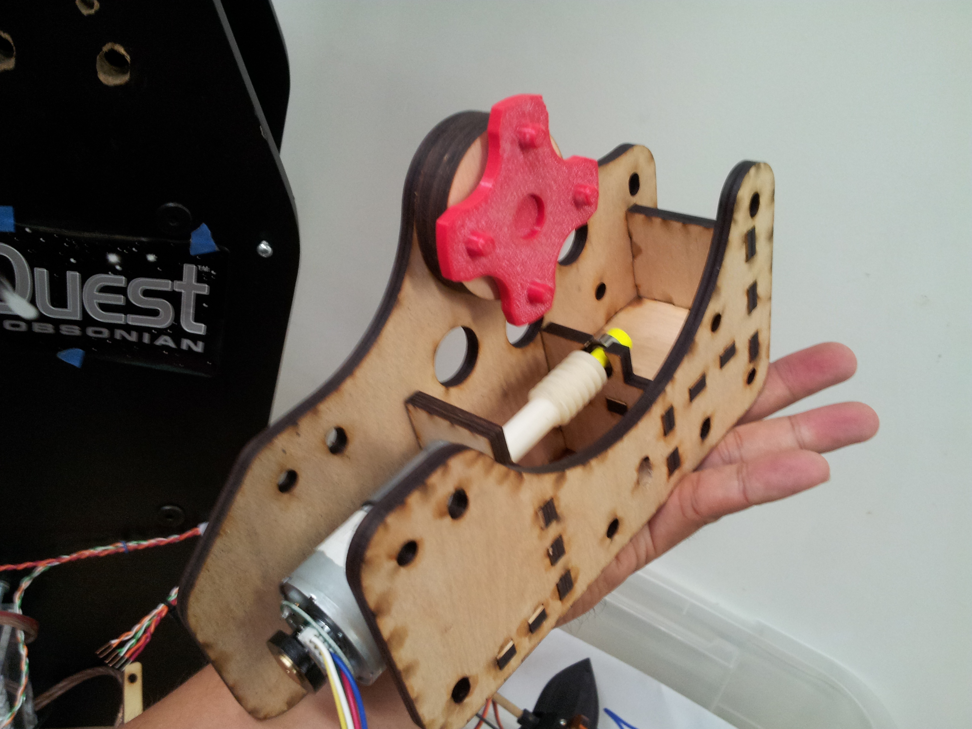
First, I removed the old motor mount :
Old altitude motor mounting hardware : acrylic plates and large metal frankenstein bolts.
Then I lasercut new mounting frame plates out of plywood. It came together rather nicely.
I designed and laser cut it myself.
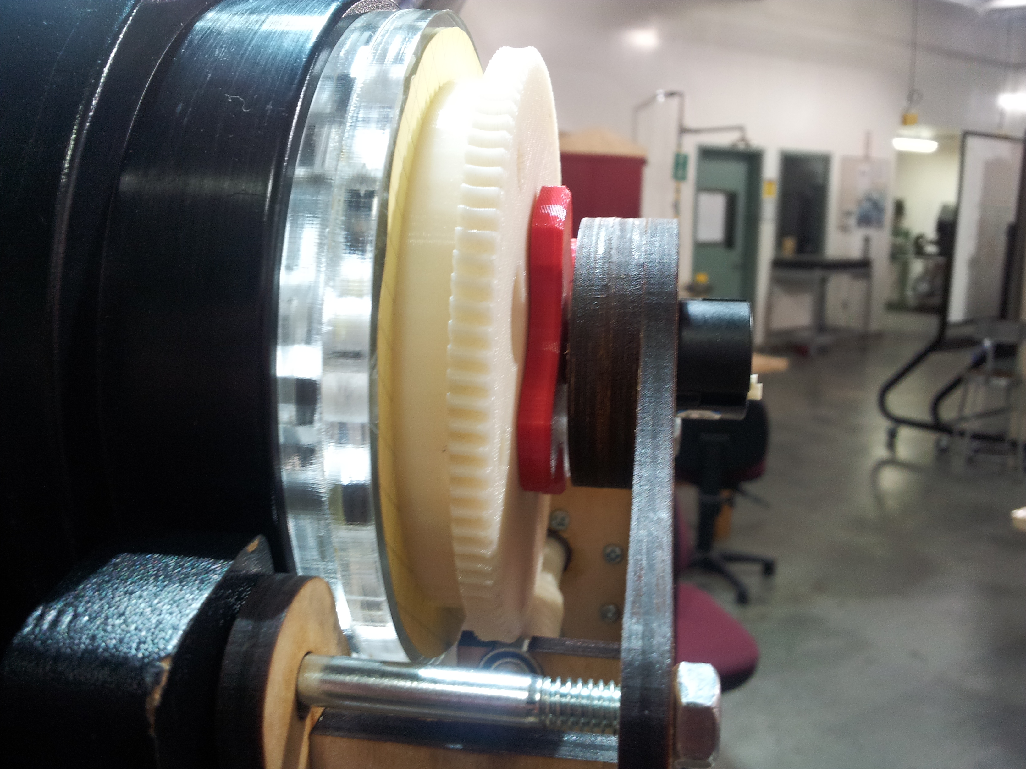
One reason I had to redesign the frame was to include a way to mount the altitude axis magnetic rotary encoder. The top plate extends over the 3D-printed worm gear. I had to 3D-print a piece that sits on the original printed worm gear, to which I attached the magnet part of the magnetic encoder. Long story short, it wasn’t too hard to design and fabricate, and now it works.
Assembled : Altitude Axis worm gear, and frame, and magnetic encoder.
And I’ve done some more changes to the driver tester’s UI.
Newer UI – made for testing the Telescope driver functions
I’m currently trying to figure out how make the telescope rotate at a specific speed (degree/second). It would require me to poll the encoder at two different times, and calculate the angle it has moved versus the amount of time passed between polls. Sounds easy enough, but I have other ideas I want to try out. In theory, most of the major imperfections and flaws of the mechanical system could be overcome with enough software. I think…
I downloaded GitHub for Windows, to work around some issue with Visual Studio not wanting to commit the master branch. Long story short – I didn’t know what I was doing, but now I have what I want. Whenever I want, I can commit whatever small changes I make to the arduino code (+ libraries), and sync it with my GitHub online repository. (I always worry what would happen to my work if anything ever happened to my laptop, but now I don’t have to)
I know my code is kinda messy, and kinda unorthodox. If anyone wants to help me improve it, I’m open to suggestions. There’s currently a lot of designing and re-designing going on. With every change I try to predict potential problems, as well as check it for logical soundness, design efficiency, code efficiency, code readability, and functionality with re-usability. I’m also trying to keep in mind just how adaptable my code might be if anyone else wanted to take on their own motorized telescope project with an Arduino.
Hmm, so I went over the type of commands that the arduino would have to process. The most important function would be the GOTO function. And how accurate it will be depends on how accurate our sensors are. Telescope Driver Version 1 will use the magnetic encoder, resolution of 5.27 arcminutes. Telescope Driver Version 2 might use the motor’s quadrature encoder, resolution of 6.1 arcseconds, potentially. But using the quad’ will require measuring the amount of backlash, and using the mag encoder is much simpler.
Rather than use double floating point degrees (which is not advisable on Arduino), or send an angular position separately as ‘degrees’ ‘arcminutes’ ‘arcseconds’ as a struct of integers and other, I’ll just send an angular position as ‘calculated arcminutes’. Basically, it’s double floating point degree multiplied by 60, to yield arcminutes. The quotient (the whole number portion) is sent as 2 bytes Int (arduino) representing ‘arcminutes’. And the magnetic encoder resolution is only 5.27 arcminutes anyways. This simplifies the math a little.
An alternative is to send position as a quantity of arcseconds, which would occupy at least 3 bytes, maybe 4. In the case of 4 bytes, it can be treated as a long (arduino) integer data type
So for Ver1, the goto byte command string will consist of 1 command byte, 2 bytes Int (arduino) that represent ‘arcminutes’ position for azimuth, 2 bytes Int (arduino) that represent ‘arcminutes’ for altitude, and 1 terminating byte of char ‘;’ – So 6 bytes total for one GOTO command.
THE ALTERNATIVE : THE EASY WAY
We only send 2-byte unsigned integer, which correspond to the magnetic encoder outputs (a number from 0 to 4095). The Arduino is left with only a few functions, with no need to calculate or convert to/from degrees or minutes or seconds. Conversions within the Telescope Driver will be easy and accurate, or as accurate can be with double floating point. But that’s not as challenging as the first method.
Although not updated with latest development, you can find my latest arduino telescope driver stuff Here
My current Arduino sketch contains code that reads in bytes from Serial. The neat thing is that I made an instruction buffer. It’s defined to hold 8 instructions at the moment, but I can easily increase it to 64. This allows the Arduino to buffer 7 instructions, whether they be movement instructions or getstatus instructions, and execute them sequentially. The Arduino Serial buffer itself is only 63 characters, that means it will only hold 63 bytes before we start overflowing. Each instruction is 6 bytes long, including terminating character ‘;’. The SerialEvent() is capable of consuming the instructions on the serial buffer as quickly as they come. Eventually, we’ll have to keep track of ‘states’ of the telescope, so we can simultaneously read in instructions from serial, buffer them internally, execute movement instructions, do getstatus instructions, pause instructions, and break instructions if necessary, And what’s really neat is that I didn’t have to rely on a QueueList class, or too heavily on String class, meaning the sketch is currently only 4.2kb. With all the free space, we can add some math and functionality, where the Arduino can ‘learn’ about it’s own sensors and motors.
*Basically, the code is at a point where it can read in ‘;’ terminated byte-string-commands. It can store in memory up to 8 byte-string-commands, but it can be expanded to much more. The ASCOM telescope driver is capable of sending byte-string-commands. There may be problems later on regarding sending and interpreting only bytes.
**I apologize in advance for the wordwrapping and bad formatting. I’m not used to wordpress with code.
//David Harbottle
//May 03, 2014
//Motorized Telescope Project
//PCC Engineering Club
#define bufflen 8#define codelen 16
//the queue works, but Arduino Serial buffer is still limited at 63 bytes
byte byteArray[bufflen][codelen] = { };int stringCount = 0; //counts the number of instructions
int i = 0; //byeArray's 2nd index counter, used by SerialEvent
int current = 0; //byteArray's 1st index counter, current instruction to run
int nextIn = 0; //byteArray's 1st index counter, index of array to write the next instruction
void setup() {
// put your setup code here, to run once:
Serial.begin(19200); pinMode(13, OUTPUT); digitalWrite(13,LOW); delay(1000); Serial.println("start");}
//round robin indexer
void currentPlus() { current = current + 1; if (current >= bufflen) current = 0;}
//round robin indexer
void nextInPlus() { nextIn = nextIn + 1; if (nextIn >= bufflen) nextIn = 0;}void loop() { if (current!=nextIn) { Serial.write("instructions left : "); Serial.print(stringCount); Serial.write('\t'); switch (byteArray[current][0]) { case 48: Serial.write("You sent a char '0'.\t"); break; case 49: Serial.write("You sent a char '1'.\t"); break; case 50: Serial.write("You sent a char '2'.\t"); break; case 51: Serial.write("You sent a char '3'.\t"); break; case 52: Serial.write("You sent a char '4'.\t"); break; case 53: Serial.write("You sent a char '5'.\t"); break; case 54: Serial.write("You sent a char '6'.\t"); break; case 55: Serial.write("You sent a char '7'.\t"); break; case 56: Serial.print("You sent a char '8'.\t"); break; case 57: Serial.write("You sent a char '9'.\t"); break; default: Serial.write("You sent a non-cmd : "); Serial.write(byteArray[current][0]); Serial.write('\t'); break; }
//clear out the instruction code
for (int j = 0; j < codelen; j++) byteArray[current][j] = 0; currentPlus(); stringCount--; Serial.write(";\n"); } delay(500);}void serialEvent(){ byte inByte;
//keep adding instructions as long as there are bytes in serial available
//and while there is at least one empty spot for an instruction in the buffer
//this stringCount+1, because nextIn points to an empty spot in the buffer
while (Serial.available() && ((stringCount+1) < bufflen)){ inByte = Serial.read(); if (inByte == ';') { nextInPlus(); stringCount++; i = 0; } else { byteArray[nextIn][i++] = inByte; } }}
Additionally, I found a way to customize the color scheme of the Arduino IDE, Dark Arduino IDE by Jeff Thompson. It’s easier on the eyes.
We are getting closer to a working telescope driver!!!! So here’s an exciting gif!
Sorry guys. This post will be brief and contain some little technical detail. Some things will be confusing because I’m still working on straightening things out.
If I could be any video game character, it would probably be Megaman
Here’s the ASCOM Telescope Driver code. And then there’s the Arduino Telescope Driver code. You’ll need both, to operate the Motorized Telescope Project. I’m putting it online so you can access it there, and watch my slow progress. It is really messy in some places, but once it’s done I’ll clean it up nice and proper.
Just to be clear, the ASCOM driver is not finished. It’s barely 15%-20% complete. I’m working on details for byte transmission protocol between Arduino and ASCOM Driver. It must also be able to process, format, and send Single Floating point 32-bit numbers over Serial communication, and receive and process it on the Arduino end. Otherwise, we can’t send local RaDec degrees to the Arduino. The alternative is we only send raw 16-bit unsigned ints, which technically works, but by principle of modular design the Arduino should receive degree-based commands, and be less dependent on the ASCOM Driver for certain tasks. This is the hardest part, but once it’s done, everything else should be alright
Arduino Serial.read() -> reads in one byte of data
C# Serial.ReceiveByte() -> reads in one byte of data
Arduino processing -> weak 'typed' language
C#, .NET -> strong 'typed' language
strong 'typed' language : less freedom, more security - also means we must use proper, logical, and hopefully efficient data type agreement throughout the entire driver
Eeep! Not much since last update… a week ago. I had to clear something off my ToDoList. Well at least I can say I got the driver connected and talking to the Arduino.
Part 1 : Arduino Code
– This code will blink the onboard LED (pin13) however many times the length of the command string that is being read on Serial, whose command string is terminated by a ‘#’ character
String temp;

void setup() {
    // put your setup code here, to run once:
    Serial.begin(19200);
    pinMode(13, OUTPUT);
    digitalWrite(13,LOW);
}

void loop() {
    // put your main code here, to run repeatedly:

    if (Serial.available())
    {
        //readStringUntil will consume the '#' character
        temp = Serial.readStringUntil('#');

        for (int i = 0; i < temp.length(); i++) {
            digitalWrite(13,HIGH);
            delay(200);
            digitalWrite(13,LOW);
            delay(100);
        }
        delay(1);
    }
    delay(100);
}
Part 2 : Telescope Driver Code
– This code snippet belongs to the Connected member object, which includes get() and set() functions. The get() just returns whether or not the driver already established a connection to the hardware. The set() checks if we’re already connected, and if not, then we establish a serial connection to the Arduino over the ASCOM.Utilities.Serial Library. Common serial parameters I use are port 26 and baud 19200. It also sends a text message to the Arduino to confirm that it’s established a connection. The next step would be to have the Arduino send back an acknowledgement text message.
private ASCOM.Utilities.Serial objSerial;

public bool Connected
{
    get
    {
        tl.LogMessage("Connected Get", IsConnected.ToString());
        return IsConnected;
    }
    set
    {
        tl.LogMessage("Connected Set", value.ToString());
        if (value == IsConnected)
        return;

        if (value)
        {
            connectedState = true;
            tl.LogMessage("Connected Set", "Connecting to port " + comPort);
            // TODO connect to the device
            objSerial = new ASCOM.Utilities.Serial();
            objSerial.Port = 26;
            objSerial.Speed = SerialSpeed.ps19200;
            objSerial.Connected = true;
            objSerial.Transmit("Hello Arduino#");
        }
        else
        {
            connectedState = false;
            tl.LogMessage("Connected Set", "Disconnecting from port " + comPort);
            // TODO disconnect from the device
            objSerial.Connected = false;
        }
    }
}
Soo yeah. That’s all I’ve accomplished for now. I’m considering writing the MoveAxis method, and the SlewToAltAz method. Eventually, I’ll be able to move the telescope by sending it a text command, such as “SlewToAltAz(123.45678, 98.76543)#” or “MoveAxis(0,0.01234)#”, with each command ending in ‘#’ character. I’m not sure how to invoke those functions through the driver test app yet, but I might have to make a form in Visual Studio. I’m thinking something like a simple CNC manual Jog feature interface.
After I can get those two functions working, then we’ll figure out how to translate between the telescope’s machine coordinates and the coordinate based on planet earth…
I’ll leave you with one of my favorite comic strips:
Ok – so let’s assume we have a functioning, working telescope. This telescope has it’s own set of coordinates in relation to it’s location on planet earth, and the exact time of day. These coordinates in theory should work with the World Coordinate System on which numerous star databases are built upon. If we want to use other star catalogs, we have to be very confident in our telescope’s coordinate system. If we direct our telescope to a known stellar object, and we see that our telescope fails to point at that object, then we have a misalignment somewhere. There are several reasons our telescope could be out of alignment : poor polar alignment, unbalanced mount, misalignment of the optical tube assembly, etc.
So, how do we correctly and accurately compensate for these errors? We use plate-solving. Plate solving is best described somewhere else. What plate solving entails is :
Pointing the telescope at a visible, known celestial body
Taking a digital photograph of what is visible
Making note of the exact time and ‘intended coordinates’
Connecting to an online star database
Finding a match for that photograph using some fancy open source computer vision software
Unimap, one of the plate solving softwares we want to try.
What follows next is we compare that match’s coordinates to the telescope’s coordinates, and apply some error correction techniques so that in the future, our telescope will point more accurately.
There are numerous plate solving softwares. Not all of them require an ASCOM driven telescope. But the fancy ones do. That’s what I’m building at the moment – the ASCOM-compliant hardware driver. (I’m actually quite busy this week, so don’t expect it to get done any time soon.)
We don’t necessarily have to write the fancy computer vision software, or dig through an online database – those parts are already done for us. But we could try to make those, if we could develop something EVEN better…
Sorry, that’s all for now. Next post ought to be better after I make some progress.
Step 1 : Download Visual Studio Community 2013 installer. Run Installer. Find out I don’t have enough space.
Step 0 : Free up 11 GB of space on C:\ drive for Visual Studio Community 2013
Step -1 : Delete hiberfil.sys by disabling the Hibernation feature in my power settings, cuz hiberfil.sys eats up 4.4GB and hibernation doesn’t really help much. But, it can only be done through the command line, in Administrator mode. Arrrggggg………
Step 2 : Run the installer again. Wait 30 minutes
Step 3 : Write on Blog.
* * *
Hello Step 3!
Today, I am installing Visual Studio Community 2013 because it’s free!! AND, I’m going to use it along with VisualMicro. This is because the folks at Arduino.cc said so. And if you don’t want to click on that last link, here’s a blurb from the page that sums it up:
Arduino IDE Plugin for Microsoft Visual Studio and Atmel Studio
Microsoft Visual Studio 2013 Community Edition (it’s free and great!)
Supports all Arduino versions 1.0 to 1.6 and the Intel Edison/Galileo
Super fast compiler with double click drill down into source code
Supports multiple .pde/.ino files in a single project
Easy set-up
Usb/wifi debugger with break and update of variables on the mcu
Educational mode
Well, there you have it. I’m going to be programming in a more advanced IDE than the one provided by arduino, using visualmicro within visual studio. And, I’m going to need this in order to build the hardware driver that will interface with the ASCOM software layer, which in turn interfaces with all the other sky mapping softwares that are publicly available and free.
I started exploring GitHub because I need a place to store my code online, and this seemed appropriate. Not only that, my code is in a state where the important bits are functional, fragile, and bug-free. I’ve only used a concurrent version control system once a long time ago, so there will probably be a learning curve. This motor library business is new territory for me, so I’ll be experimenting with lots of bad code. Don’t expect me to arrive at a final version any time soon.
This is good news. This is evolution. I now have a github.
* * *
Let’s move onto the code, shall we? There was one major issue concerning the 12-bit magnetic encoder. As you rotate the magnet beneath the encoder, it outputs some value corresponding to the angle of that magnet relative to the encoder. The magnetic encoder outputs a value between 0 and 4095, because the encoder can count as fine as 4096 degrees per revolution – much finer than simply 360 degrees per revolution. The problem is, it only outputs a number between 0 and 4095. So it just wraps back around to the beginning once you cross over 4095, and vice verse.
This doesn’t work with the way I’m doing the GOTO function, so I started with some notes. I needed a way to measure the angular distance from the current angle to the angle we want it to be :
clockwise, distance
  if target < current
    distance is target + 4096 - current
  if target > current
    distance is target - current
And I turned it into this :
int getCWDistance (int current, int target) {
  return (target - current + ((target < current)*4096));
}
If you noticed, there’s a boolean statement within the last half of the return statement : (target < current). Based on the notes, the distance will always be (target – current), but in certain cases you have to add 4095 otherwise we’ll end up with a negative number that doesn’t make sense. When the boolean statement (target < current) gets evaluated, the value within those parenthesis becomes true/false. But in C, true also has a numerical value 1, and false also has a numerical value of 0. We can actually apply the boolean values of true and false in mathematical statements, such as I did there.
So now we have a way of measuring the angular distance of where I am pointing, to where I want to point to. My simple GOTO function tells the motor to run at full speed until it gets closer to the target angle. Then it slows to half speed until it gets to within several degrees, and then it moves at it’s “slowest capable speed” until it reaches the actual target angle. So far during testing, it’s been able to hit the target angle spot on, plus or minus 1 if the table shakes. The momentum of the entire telescope may be a factor. But that is not a big problem. Also, none of the bearings or gears are greased. That is a big problem…
In other Code News : I managed to get the Arduino to read in a number over Serial communication. I found the function parseInt() in the Serial Library, so it makes my job a lot easier. Basically, you can type in a number, press enter, and the telescope will rotate it’s base until it arrives at that angle. It’s a lot more exciting than it sounds, so if I remember, I’ll take video next time. So far, I got the base to rotate left and right. I haven’t gotten to making the telescope tilt up/down yet. But implementing that won’t be difficult, now that everything else is working.
Once the altitude motor GOTO function is working, all we need is to get the Raspberry PI online and connected, so it can start sending some real numbers.
Looking ahead, our next big challenge will be finding a suitable program to do plate-solving : Plate-solving is a method in which we use a digital photograph of what we see through the eyepiece, pick out known constellations, and orient ourselves in relation to the universe.
Maybe I’ll pick something more interesting to talk about next time.